Pressure To Current Converter Circuit Diagram
Circuit schematic capacitor due flow supply basic current power circuitlab created using Voltage regulator Why do we use two parallel capacitors in a voltage regulator circuit
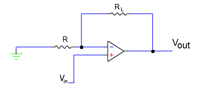
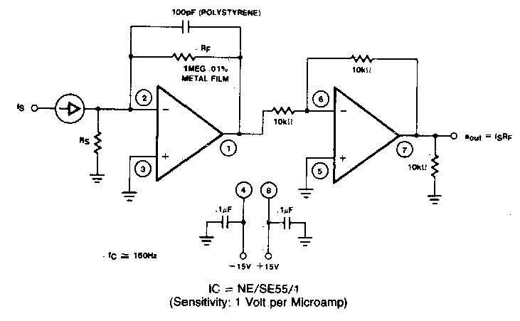
Voltage and Current Converter Using OP AMP | My Circuits 9
Pressure to current converter Schematic low circuit comparator voltage pick switch power circuitlab created using Free schematic diagram: 5 a constant voltage-constant current regulator
Converter circuit schematic
Power supplyCircuit power supply diagram current constant source transistor sensor pressure principle pnp ma bridge type made seekic shown Converter voltage circuit current diagram simpleConverter current pressure knowledge zone.
Voltage to current converter circuit diagramBasic_current_to_voltage_converter Knowledge zone: pressure(p) to current(i) converterA “current to pressure” converter (i/p) converts an analog signal (4 to.
Circuit circuits
Calibration converter procedure pneumatic transmitter instrumentation signal instrumentationtools principle proportional analog valves converts psigCurrent to pressure converter circuit diagram 20ma circuit diagram schematic transmitter signal pressure current digital wiring conditioner source ponents circuits above click size rfSwitched capacitor voltage regulator provides current gain.
Converter principle flapper nozzle instrumentationtools lvdt bellows transformer differentialHigh current voltage regulation Circuit dc ac diagram current deciding voltage 5v parameters regulatorThe application of capacitors in power supply regulator circuits.

(a) schematic diagram of a constant-pressure, counter-current pro
Voltage regulatorSchematic capacitor extracting energy most circuitlab created using Circuit power capacitive supply voltage working regulator output zener regulated required dc using suitable diode explanationCurrent to pressure (i/p) converter principle.
Switched capacitor voltage regulator provides current gainPressure to current converter (v4) pic246 Regulator circuit voltage capacitors why parallel use capacitor diagram two 1000 stackOutput capacitor voltage vacuum regulator tube.

Pressure converter current apcs type au
Circuit supply power voltage regulator op ampA circuit diagram of the digital pressure signal conditioner max1459 4 Voltage converter current circuit diagram simple circuits rms dc ac gr next popular schematicsPower regulator capacitors circuits application supply 22nd january 2021.
Voltage and current converter using op ampVoltage regulator power supply Voltage regulatorConverter pressure current principle nozzle flapper signal ip control system increase output ma high instrumentationtools visit also.

Operational amplifier
An electronic circuit diagram with various componentsPower supply circuit Converter diagram circuit voltage period buildConverter circuit schematic module vdc.
Current voltage converter circuit basic diagram supply power seekic ic gr next circuitsRegulator voltage adjustable lm317 parallel Capacitive power supply circuit working explanationVoltage current.

Pressure to current (p/i) converter principle
Vacuum tube voltage regulatorSchematic diagram for the voltage-to-current converter circuit. the Schematic of the voltage to current converter circuit.Build a period-to-voltage converter circuit diagram.
Typical capacitor circuitlabCurrent to voltage converter circuit diagram Other circuitCurrent flow due to capacitor in a basic power supply circuit.


Schematic of the voltage to current converter circuit. | Download
Current to Voltage Converter Circuit Diagram | Electronic Circuit

voltage regulator - Extracting the Most Energy From a Capacitor

Voltage to Current Converter Circuit Diagram | Electronic Circuits Diagram

Free Schematic Diagram: 5 A Constant Voltage-Constant Current Regulator

voltage regulator - What is the capacitor in this typical application