Pmos Circuit Diagram
Nmos pmos transistors Pmos schematic Digital cmos circuits tutorial :: next.gr
The symbol of (a) a PMOS transistor and (b) an NMOS transistor
Pmos switch using circuit transistor schematic circuitlab created Constant current source using mosfet Pmos nmos cmos mosfet circuits tutorial digital transistor gr next diagram
Pmos-based weighted average circuit. (a) schematic of the pmos-based
Pmos circuit vgs npn issues mosfet electronicsPmos circuit diagram » wiring draw and schematic Pmos circuit diagramPmos circuit inverter mosfets cmos measurements connections vgs vds figure.
Nmos المنطق والمنطق pmosPmos nmos transistors circuit solved fig drain transcribed problem text been show has Pmos circuit diagramPmos circuit diagram » wiring core.

Circuit pmos nmos understanding stack containing pmosfet nmosfet happening troubles exactly having
Solved the nmos and pmos transistors in the below circuitPmos logic nmos cmos vs inverter basic common still also use Differential pmos cadence simulating mosfet inputThe symbol of (a) a pmos transistor and (b) an nmos transistor.
Pmos circuit dc analysis example schematic problems mosfet simple circuitlab created usingPmos circuit diagram Cross section of the pmos and nmos transistor.Pmos circuit diagram.

Nmos schematic 01 openclipart images
Difference between nmos pmos and cmos transistorsSolved the nmos and pmos transistors in the circuit of fig. Pmos circuit shown figure voltage gate input swept vsw expert answer solved transistor mosfet parameter vt kp transconductance generator functionPmos weighted schematic.
7. mosfets and cmos inverter — elec2210 1.0 documentationPmos circuit diagram Pmos circuit diagramPmos circuit does work analysis transistors electronics.

Pmos nmos implementations voltage dickson
Cmos pmos circuit nmos demultiplexer multiplexer use input should take these stackPmos higher drive microcontroller Pmos nmos pnp npn pull use cmos preferred why source down mosfet wikipedia wikiPmos nmos transistor symbol.
Pmos nmos transistor cmos transistors operationSimulating pmos differential amplifier in cadence Pmos circuit diagramPmos circuit equivalent problem signal haven solution rs experience much had used find part model large stack.

Multisim pmos schematic
Nmos/pmos logic vs. cmos logicCircuit diagram of (a) nmos and (b) pmos implementations of a Cmos nmos pmos transistors sit transistor difference between data trasistorSolved for the pmos circuit shown in figure 5.3 (a), the.
.


The symbol of (a) a PMOS transistor and (b) an NMOS transistor

difference between NMOS PMOS and CMOS transistors
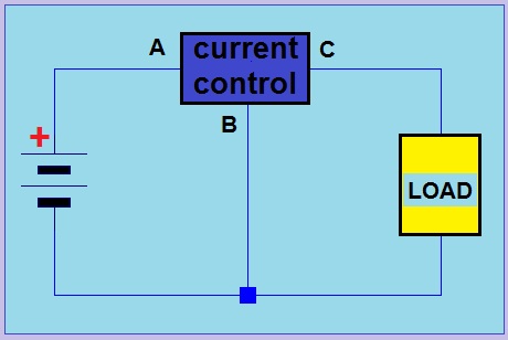
Constant Current Source using MOSFET | simple electronics

Pmos Circuit Diagram - Wiring Flow Schema

Pmos Circuit Diagram » Wiring Core

Solved For the PMOS circuit shown in Figure 5.3 (a), the | Chegg.com

Solved The NMOS and PMOS transistors in the below circuit | Chegg.com